

Introduction: DIY Arduino Macro Keyboard - Increase Your Productivity!

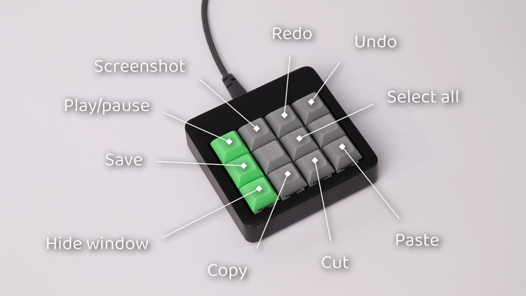
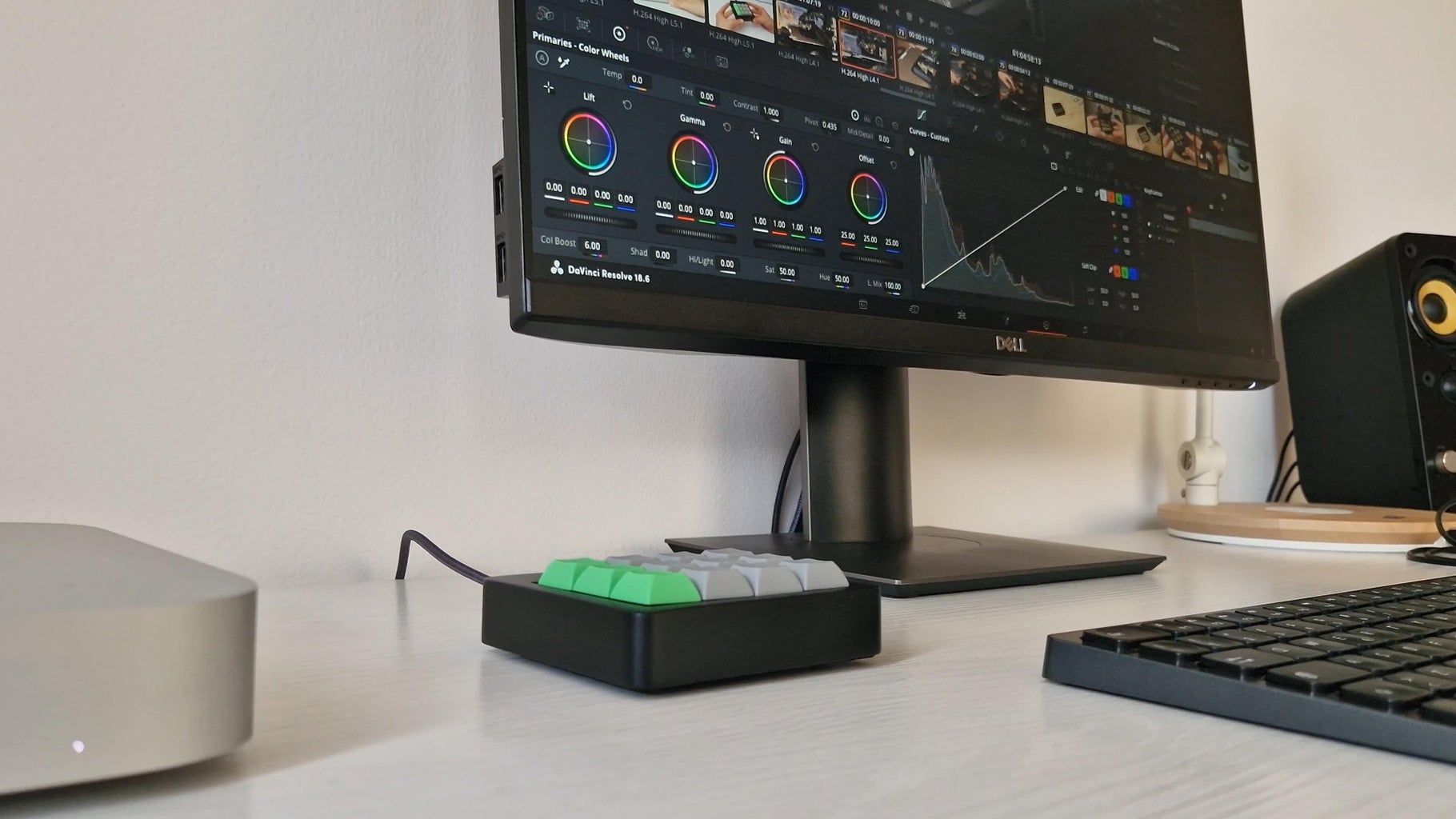


Hi, I am Giovanni Aggiustatutto and welcome to this Instructable! In this guide we will build a 12-key macro keyboard for our computer with an Arduino. When working on the computer, having a macro keyboard is very useful because you can access the shortcuts and the functions you use more often just by pressing a single button. For example, you can have a key of the macropad associated to the CTRL+C shortcut, the one for copying text and files. When you press that key, the Arduino inside the keyboard will tell the computer that you have pressed both the CTRL and the C buttons on your keyboard. In my case I have included some shortcuts to manage the file explorer, music, and access classic functions such as copy and paste, save, undo, and repeat, but of course the buttons can be customized to suit our needs. For example, we can add to the macro keyboard the shortcuts for a specific software we often use. At the time of writing I have been using my macro keyboard for over 2 weeks, and I can assure that it makes you save quite a bit of time and it is really convenient, both for video editing and for general use.
The keyboard we will build today has 12 buttons to which we can associate the shortcuts we want. Anyway as complicated as this project sounds it is actually quite simple, both the electronics and also the software.
As always, I've also made a video about this project, that you can find on my YouTube channel (it has English subtitles).
Supplies

To make this project, I used:
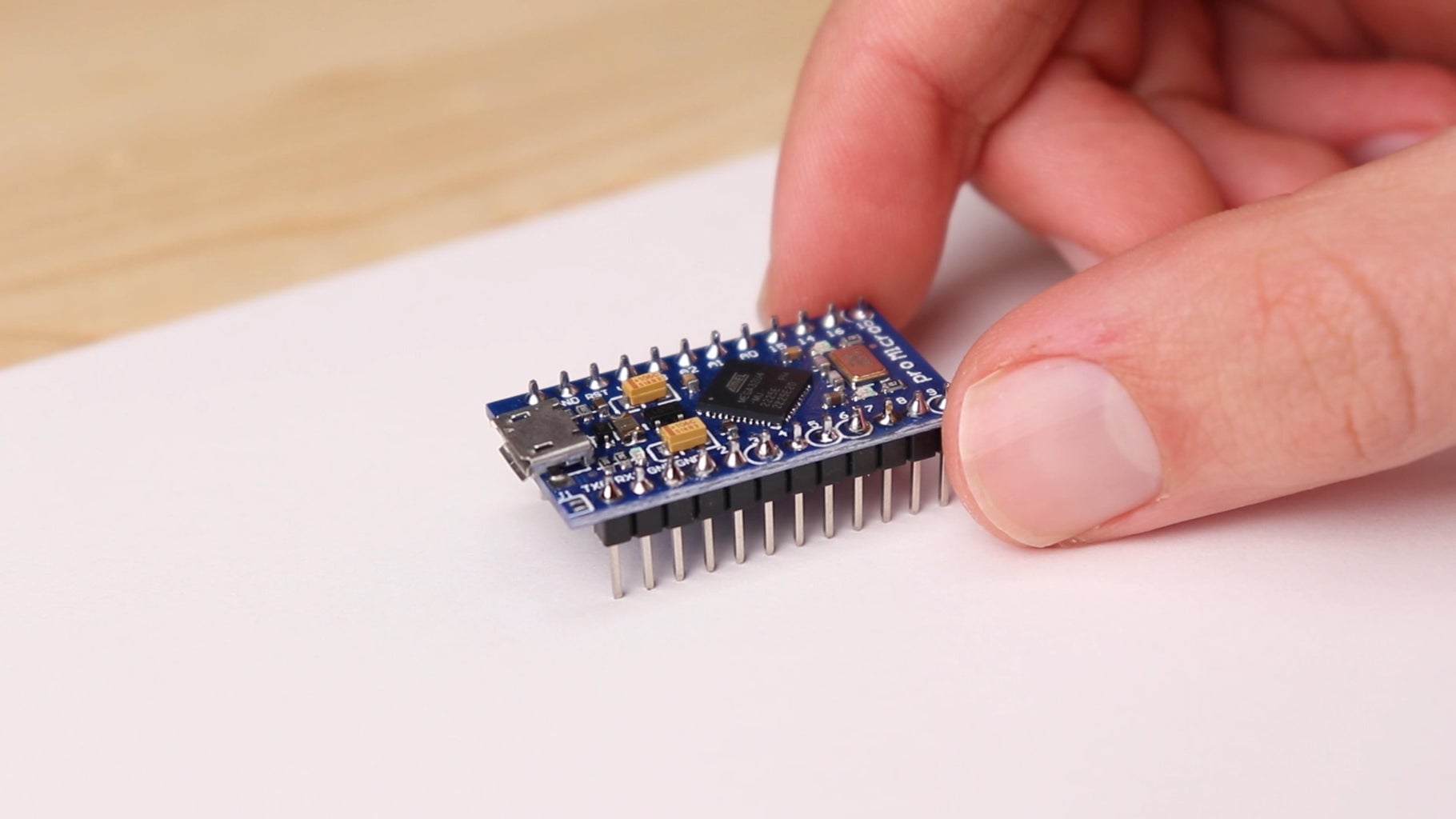
- Arduino Pro Micro (link here)
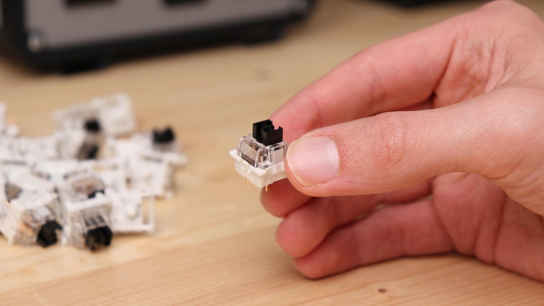
- 12 Cherry MX style keys (link here)
- 12 DSA style keycaps (for my project I used green and grey ones, but you can choose the colors you want; link here)
- Wire (26 AWG)
- Bare copper wire
- Black spray paint
- Filler primer (optional, but makes painting easier)
- 2 M3x12 mm screws
- 2 M3 threaded inserts
Tools I used for this project:
- 3D printer with black PLA filament
- Soldering iron
- Hot glue
- Sandpaper (180, 320, 600 and 1200 grit)
- Screwdrivers, pliers and other basic tools
Step 1: Design Choices
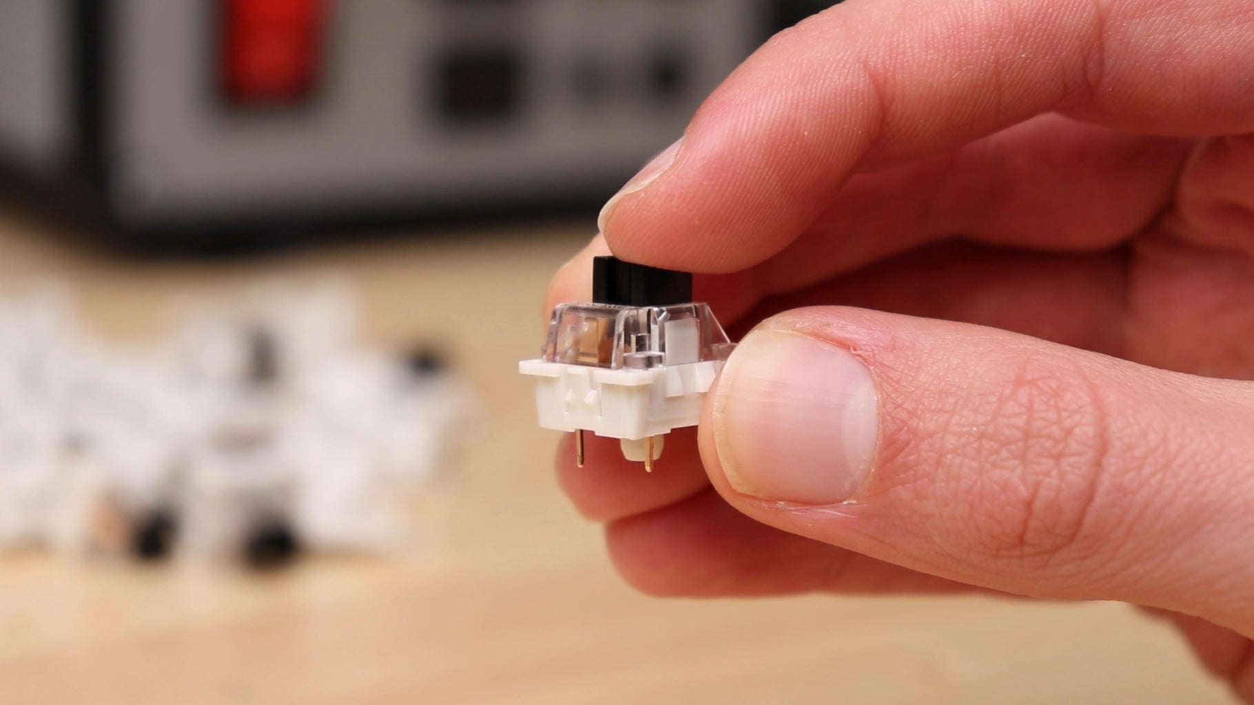
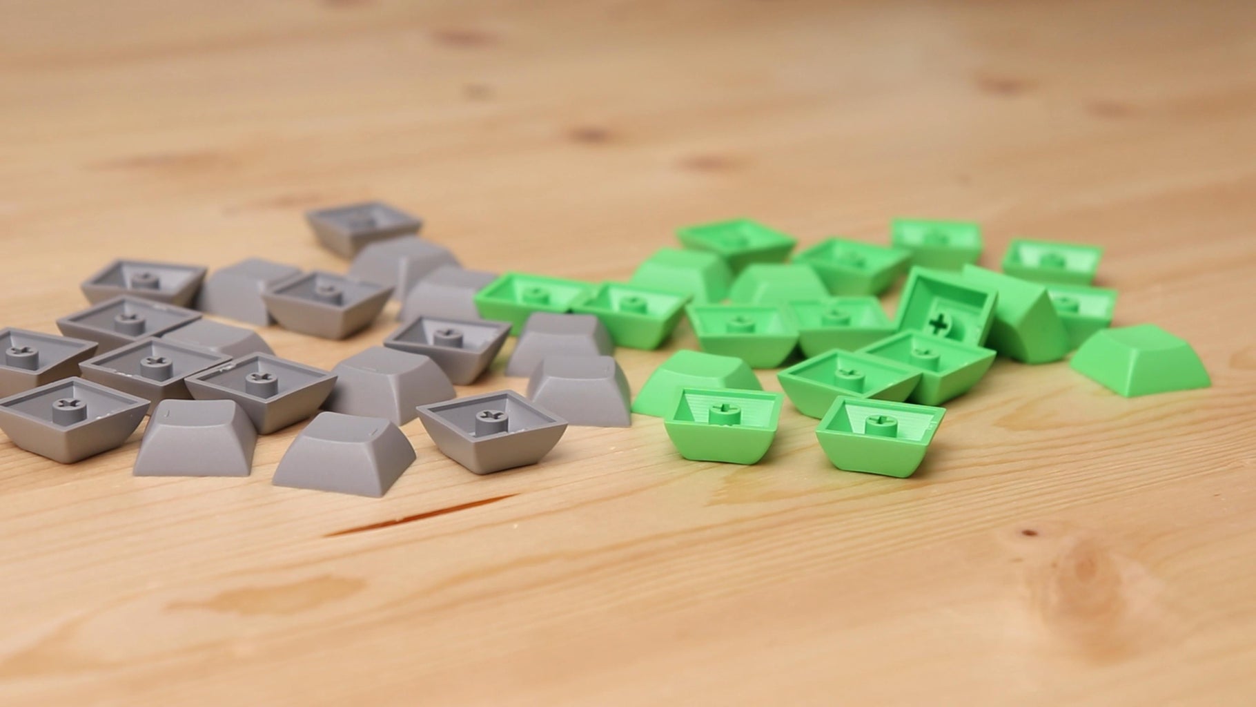

Taking inspiration from other projects, I decided to make my macro keyboard using 12 keys, with a layout of 4 keys horizontally and 3 vertically. The keys on a keyboard are actually made of two parts: we have the actual switch, which will be later connected to the Arduino, and what is called a keycap, which is put on top of the switch. The keycaps generally are printed with the letters and numbers we have on a keyboard, whereas the ones I chose have no printing at all. In this way I was thinking of drawing an icon on the key myself, and I even tried it, however there were two problems: first of all drawing such small icons by hand is really difficult, and also I thought putting icons on the keys would kind of ruin the clean design of the keyboard. So I simply decided to leave the keys without icons, also because having only 12 of them, remembering the position of each key will not be a problem. Another solution would be to print the icons on the keycaps, but the technique for that seems to be quite complex.
Step 2: 3D Printed Parts

Now that I had the keys, all I needed to build the keyboard was the 3D printed enclosure. Along with the keys, this is the part that will give the keyboard its aesthetic look, so designing it took some work. After some iterations I decided to follow the design of the Mac Mini I have on my desk, which is a simple rectangle with rounded corners.
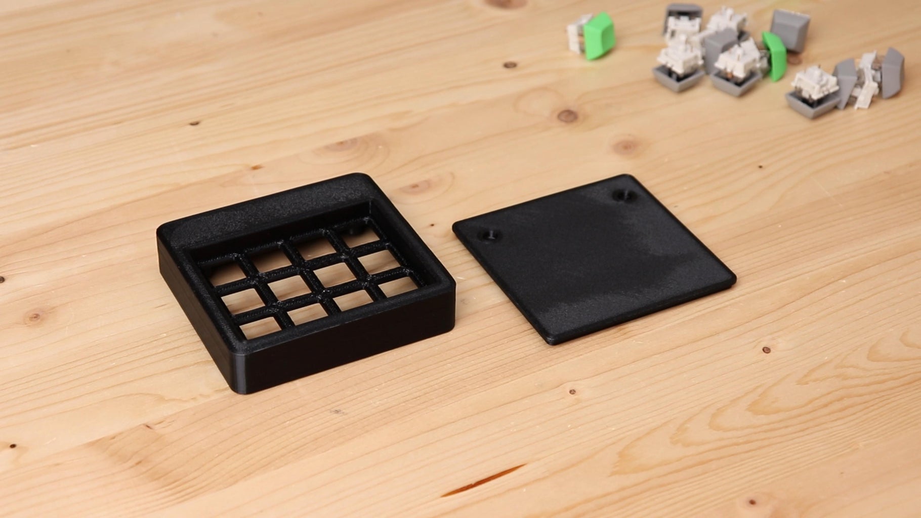
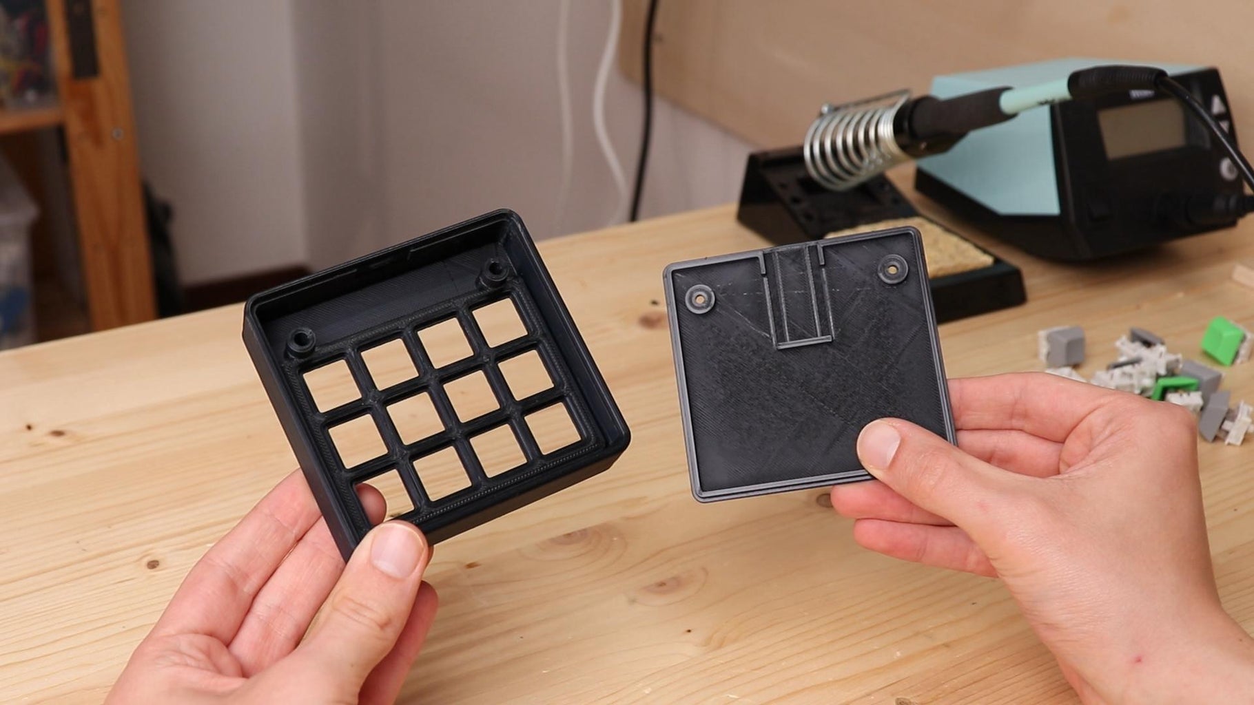
I 3D printed the enclosure of the keyboard and its cover with black PLA. The enclosure has a grid in which the keys can be mounted. Below, there is space for the Arduino and the wiring. The USB port of the Arduino will be accessible from the hole in the back of the enclosure, in order to connect the Arduino to our computer. The cover can be inserted from the bottom side of the keyboard, and will be secured later with two screws. This way, the junction between the enclosure and the cover will not be visible.
The STL files for 3D printing are below.


Step 3: Finishing

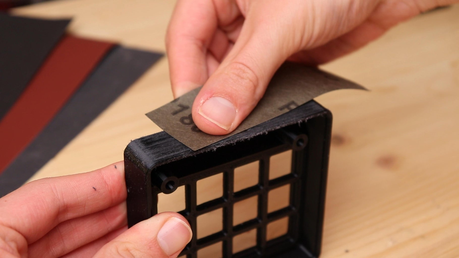
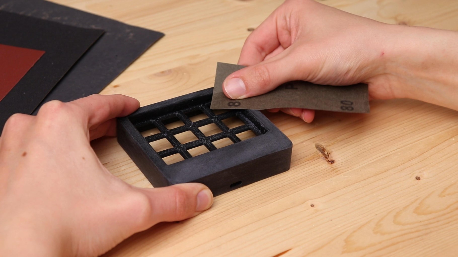
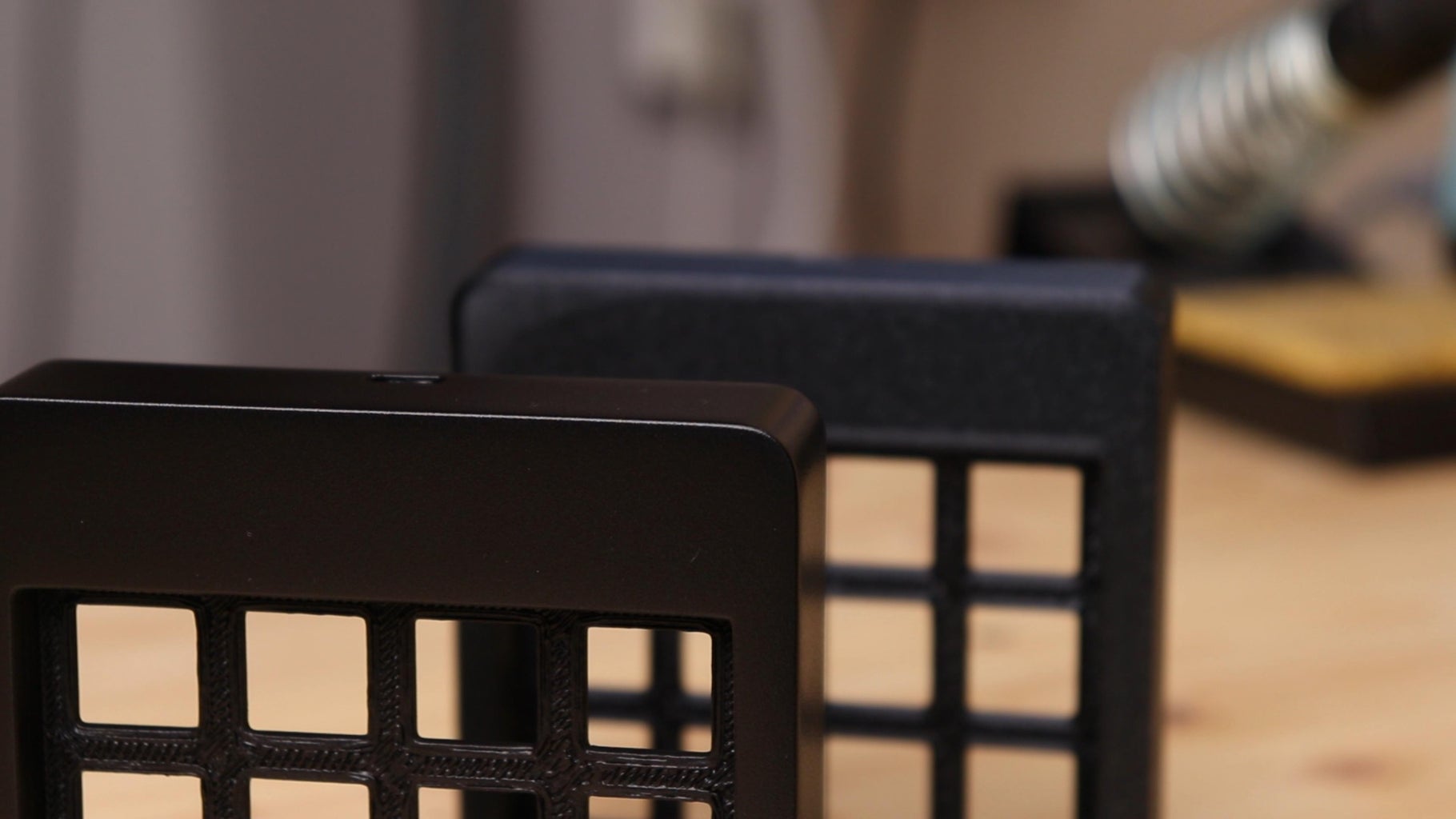
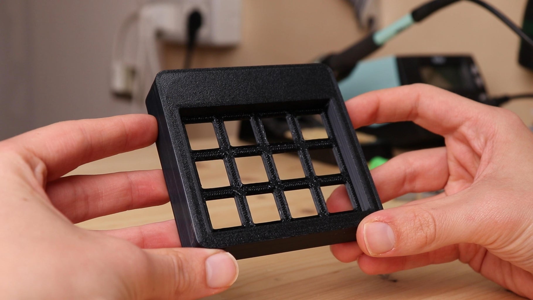
As good as the 3D printed part turns out, the finish left by 3D printing is shiny and with layer marks. That wouldn't be a problem for a tool to use in my workshop, but for an object to keep on my desk I wanted a more clean finish. So I decided to paint the 3D printed part. First, I sanded it with 180 grit sandpaper until the layer marks were completely removed. I then switched to a 320 and finally a 600 grit sandpaper. It was a really time consuming process, but this way I got a perfectly smooth finish ready to be painted. To paint the enclosure, I used a matte black acrylic spray paint. I gave the 3D printed part three coats, and between coats I lightly sanded it with a 1200 grit. Before painting the part I did not use a primer, but for a better result with less effort I recommend using it.
Once the paint dried the result was amazing, even if I had not used a primer. In the pictures above you can see a comparison between the 3D print finish and the painted one.
Step 4: Assembling
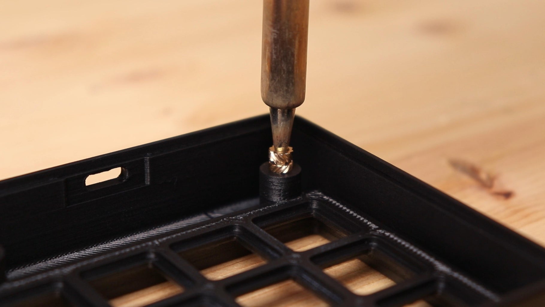
At this point we can assemble the keyboard. First, I put M3 threaded inserts in the two holes that are on the inside of the 3D printed part. These threaded inserts will later be used to close the lid of the keyboard with M3 screws.
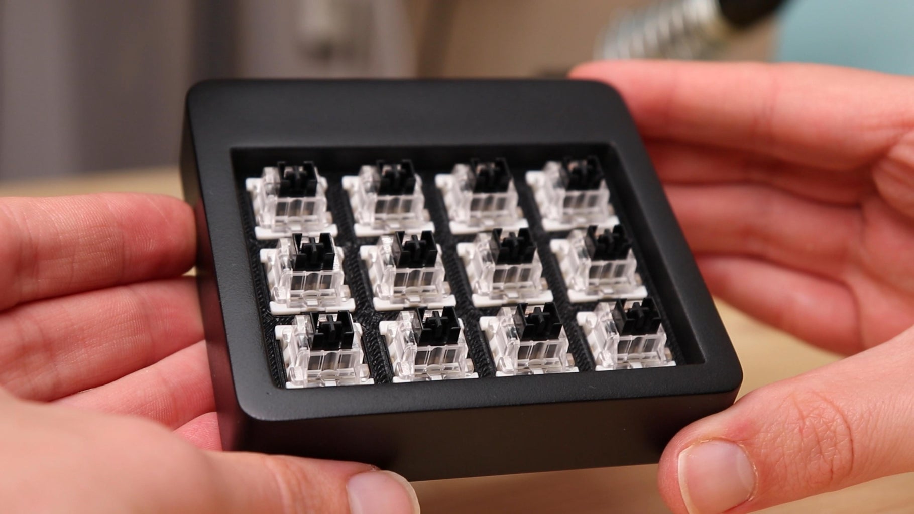
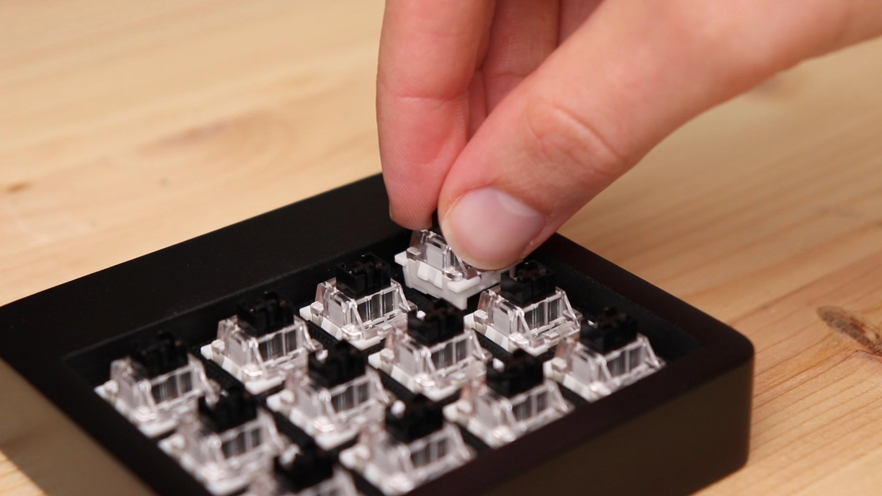
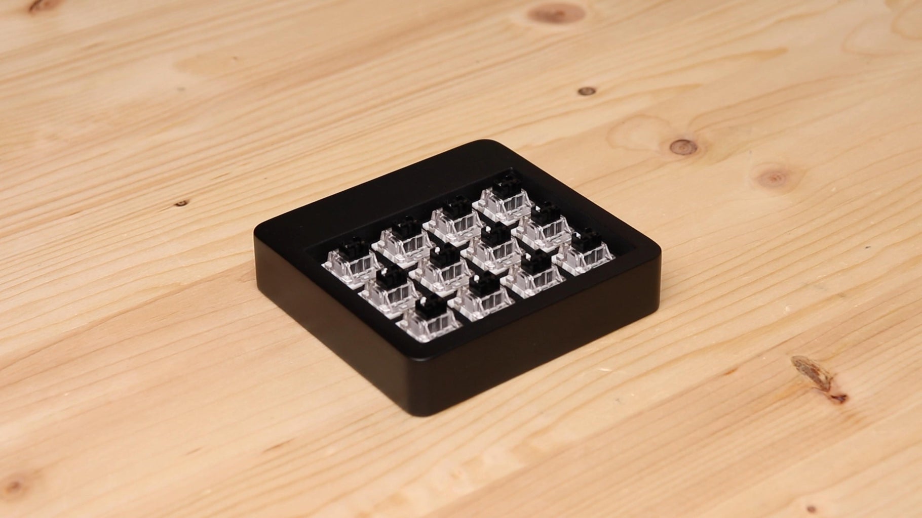
Then I inserted the 12 keyboard switches into the grid of the 3D printed keyboard enclosure. The fit is quite tight, so the switches interlock into the 3D printed part and no glue is needed.
Step 5: Electronics
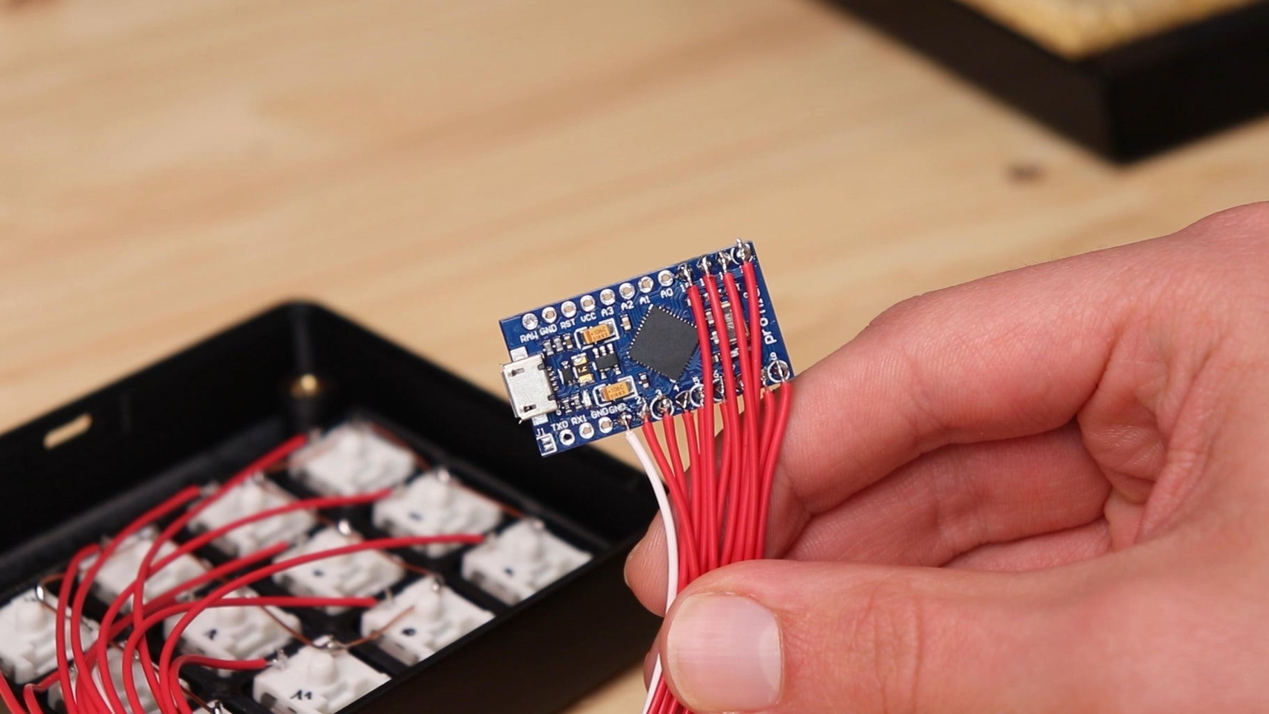
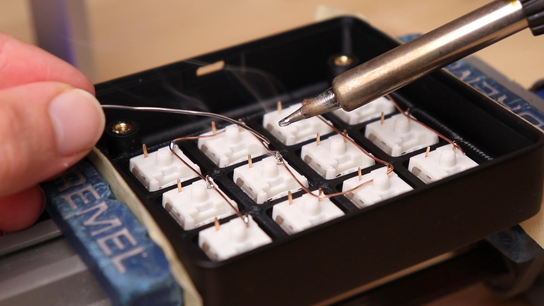
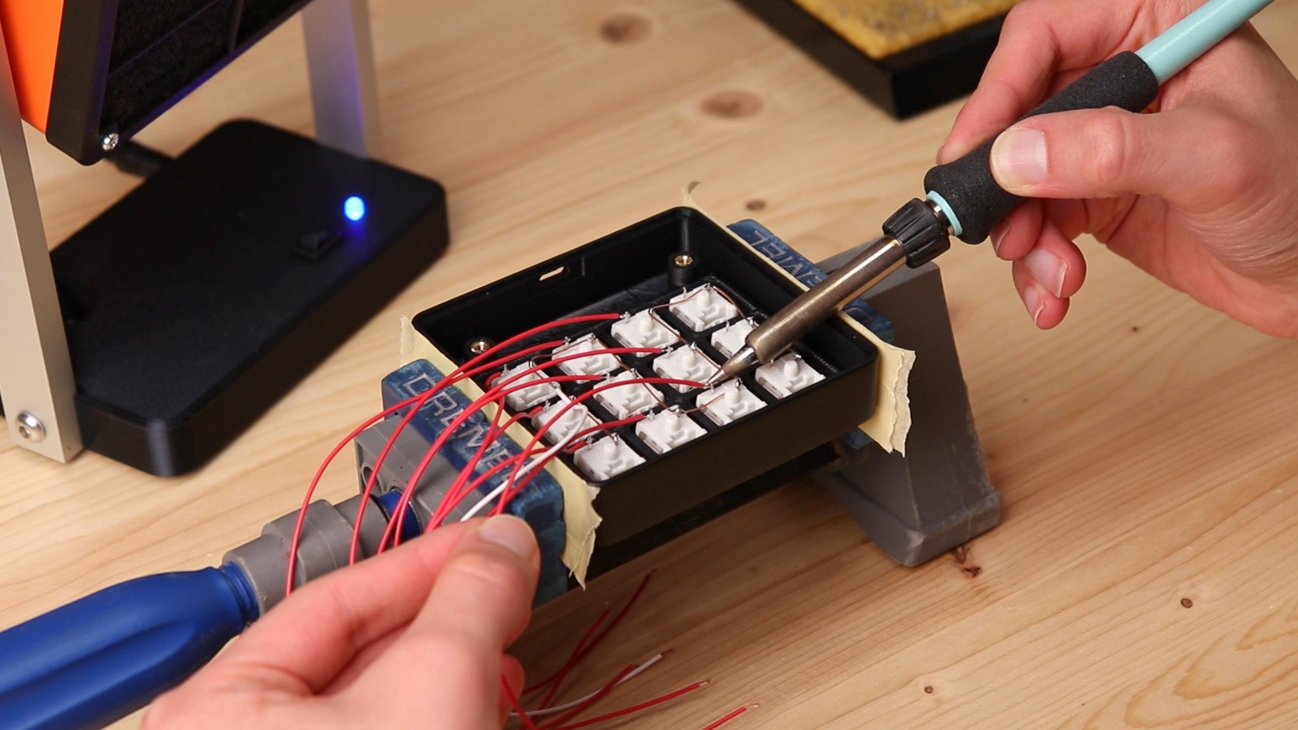
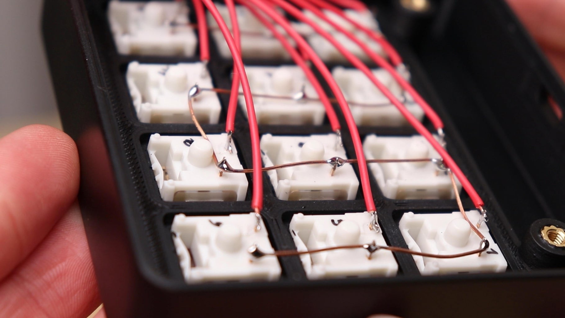
At this point we can make the electrical connections between the keyboard switches and the Arduino, which as we will now see are very simple. Each one of the keys will be connected between the GND and one of the digital pins of the Arduino, and of course this connection will be repeated for all of the 12 keys. So we need to bring the GND of the Arduino to all the switches. To do this I used a copper wire that I soldered to one of the two pins of each one the switches. Then I prepared twelve 10 cm-long pieces of wire, which I soldered to the free pin of all 12 buttons. In order to be able to put the Arduino board into the keypad, I removed the jumper connectors that were soldered onto the PCB. To the copper wire that connects all of the switches, I soldered a piece of wire, that I connected to the GND pin of the Arduino. Then I soldered the wire coming from each button to a pin on the Arduino, avoiding pins 0 and 1, which are for serial communication. As you will have noticed with the 12 switches we are using all of the available digital pins of the Arduino. In case you want to add more buttons to your keyboard, you can use the analog pins or experiment with a matrix connection, that however requires quite a few changes to the code.
For the connections I followed the wiring diagram you can find below.
Attachments

Step 6: Final Assembly
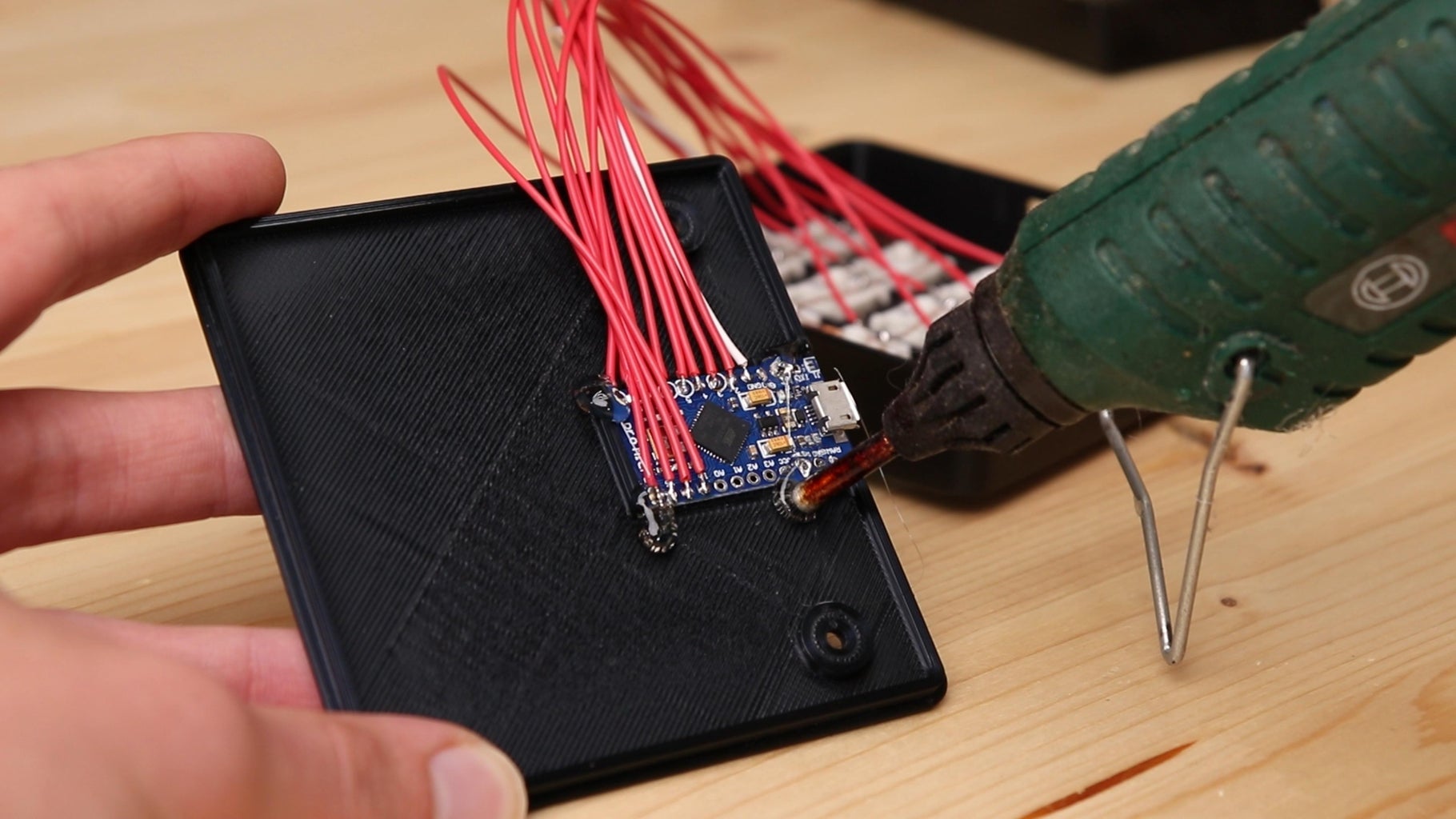
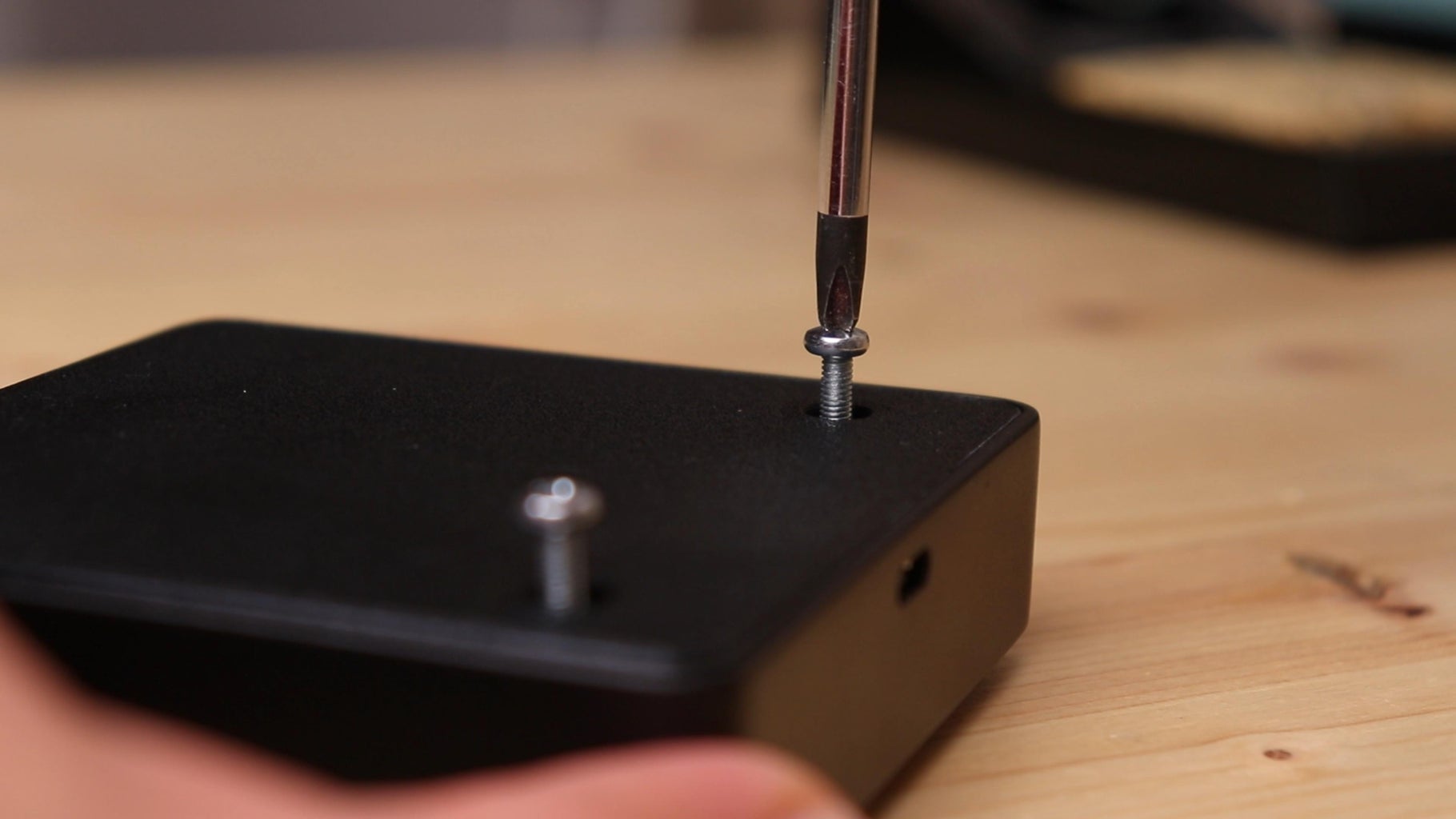
Now that the electrical connections are finished, I positioned the Arduino onto the keyboard lid following the small plastic guides, before securing it with some hot glue. It is important to mount the Arduino quite precisely, because the USB port will have to align with the hole in the keyboard enclosure.
I closed the lid of the keyboard and secured it with two M3 screws, screwed into the threaded inserts. Underneath the keyboard I put four non-slip feet, which raise the keyboard a little bit from the table, creating a small shadow that I think looks very good.
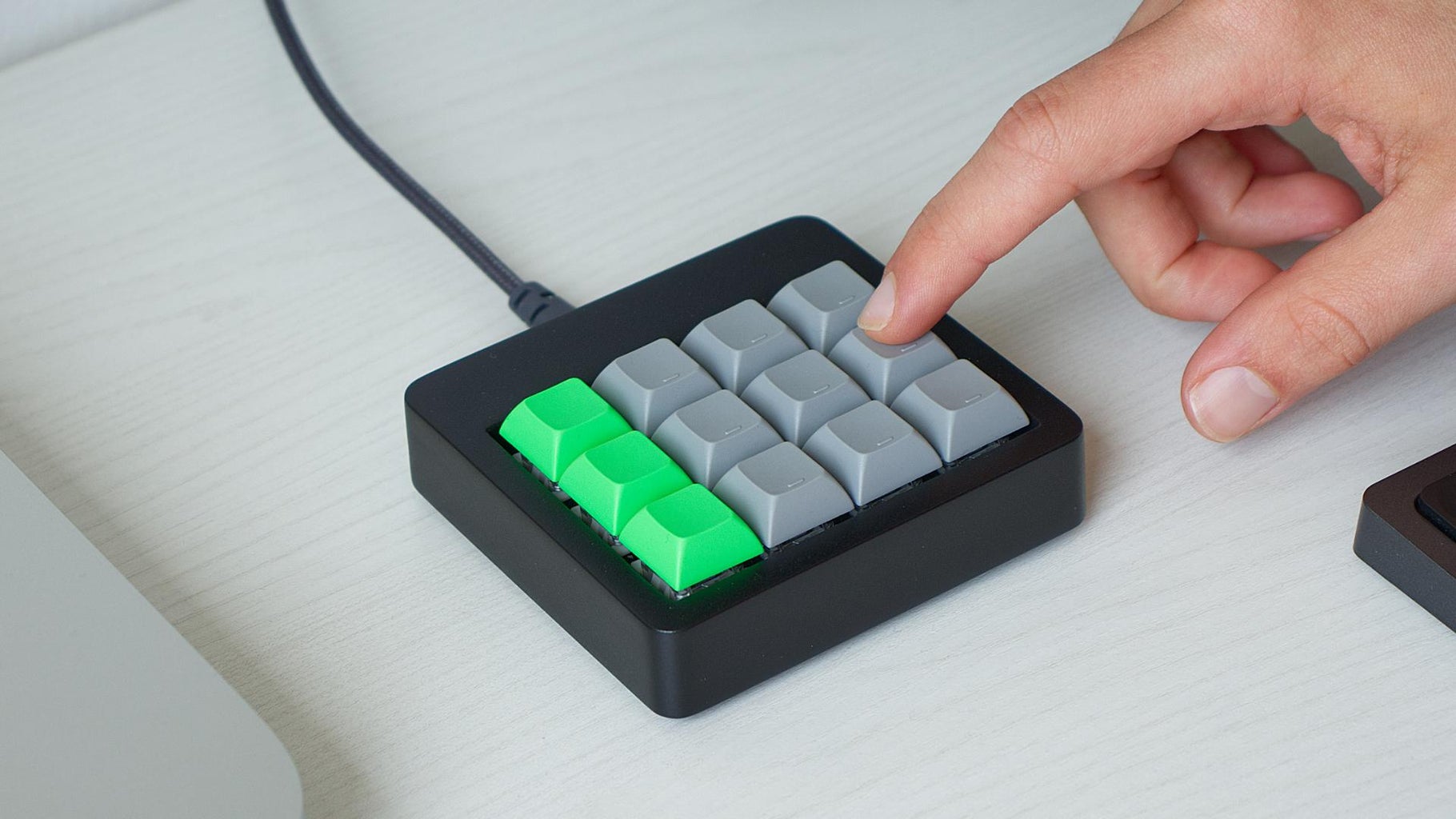
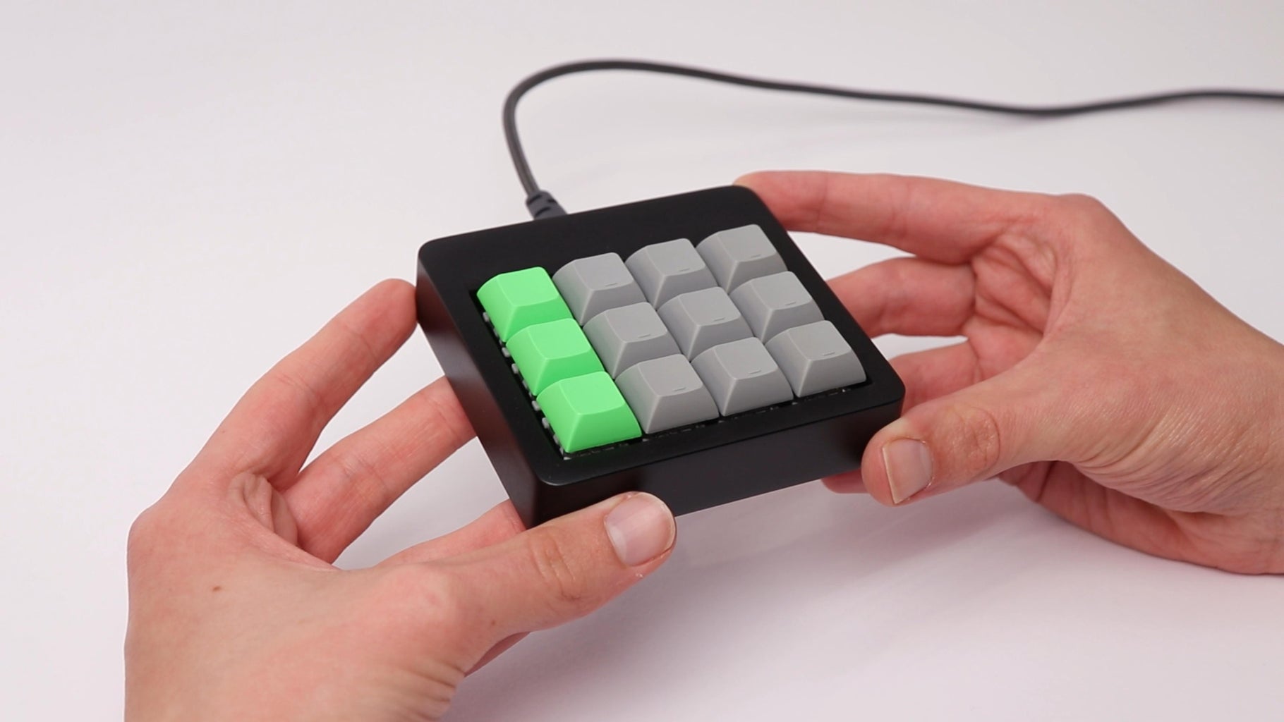
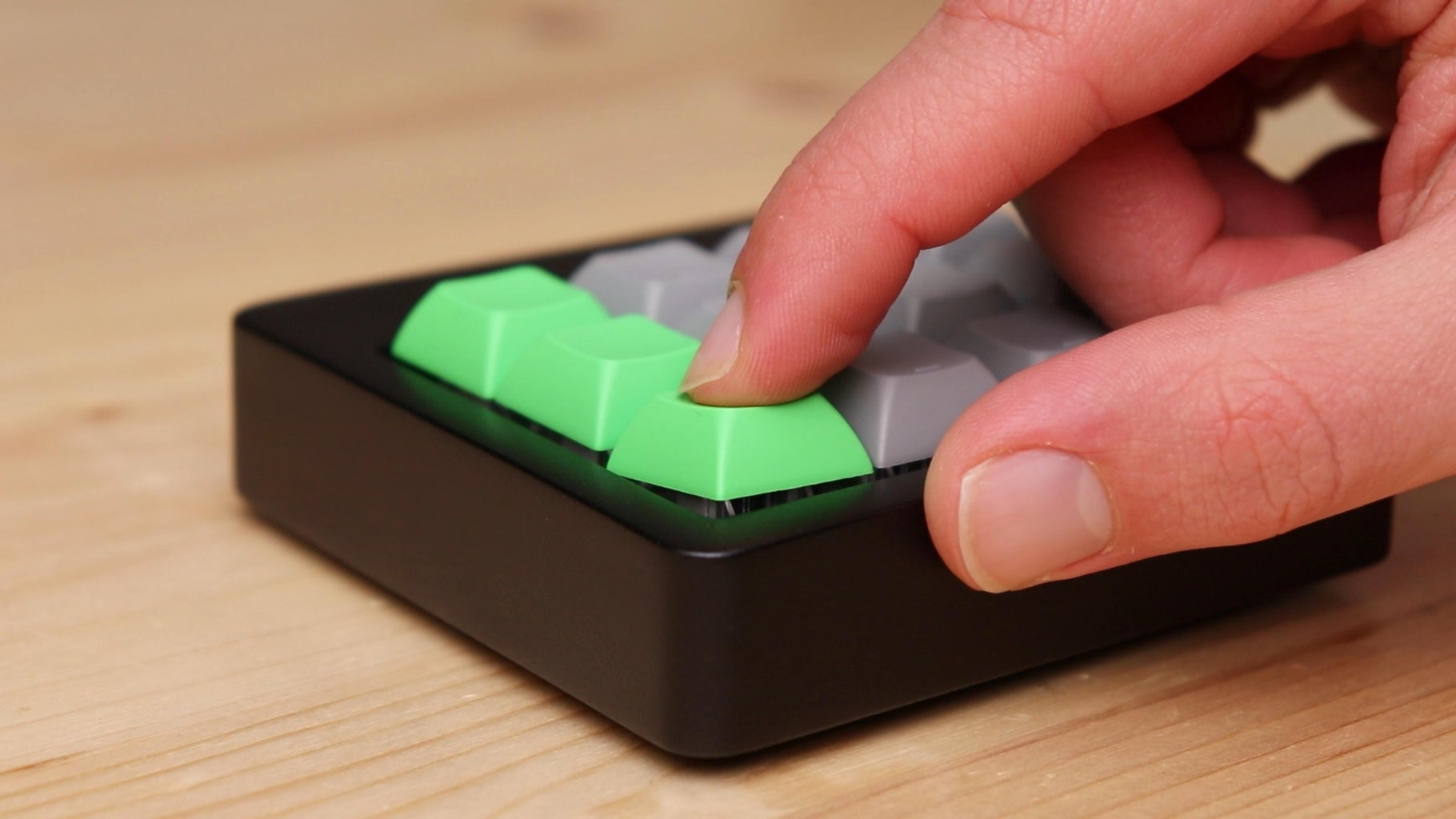
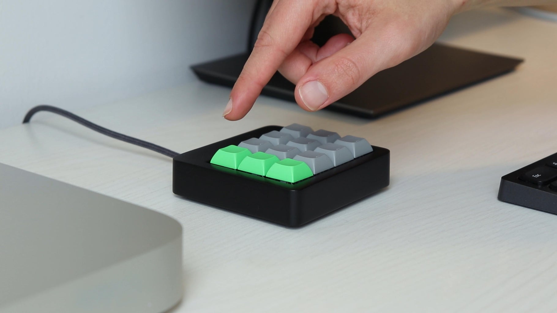
As a last thing, I inserted the keycaps on the switches. For my keyboard, I created a pattern with three green keycaps on one side and the other ones grey, which I think looks very good. This also helps remembering the position of each key. Of course you can choose the pattern and the colors that you prefer.
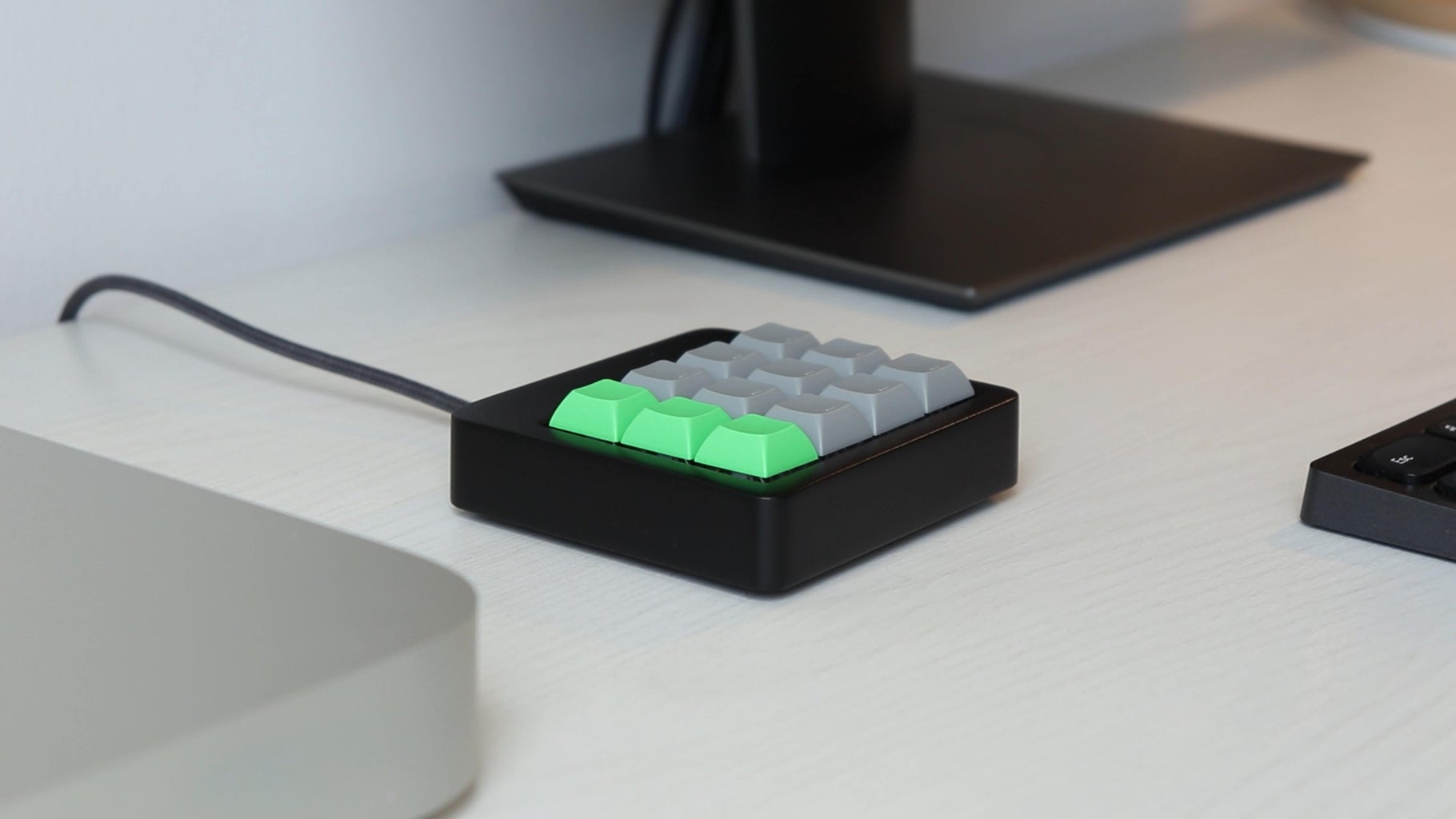
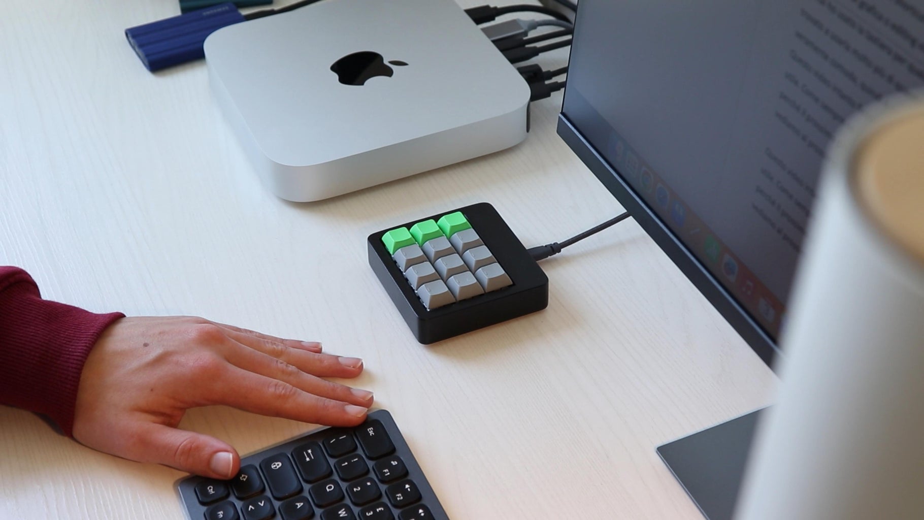
The keyboard is finished, and I really like how it turned out. Its clean design perfectly matches the other devices I have on my desk. On the back of the keyboard we have the USB port of the Arduino, which we can use to connect the keyboard to our computer.
Step 7: Code
The last step before having a functional keyboard is writing the code for the Arduino. The Arduino needs to be detected by the computer as a regular USB keyboard. When we press one of the switches of the macro keyboard, for example the "copy" button, the Arduino is actually sending to the computer the key combination associated with that button, in this case CTRL+C.
Here's the code for the Arduino explained step by step. At the end you will find the full code to copy.
#include "HID-Project.h"
To make the Arduino communicate with the computer I used the library "HID project". This library allows the Arduino to be detected by our computer as a normal keyboard. To see the examples for all the functions, check out the GitHub page of the author.
const int switch1 = 2;
const int switch2 = 3;
const int switch3 = 4;
const int switch4 = 5;
const int switch5 = 6;
const int switch6 = 7;
const int switch7 = 8;
const int switch8 = 9;
const int switch9 = 10;
const int switch10 = 16;
const int switch11 = 14;
const int switch12 = 15;
At the beginning of the sketch, I defined variables with the pins the keyboard switches will be connected to.
void setup() {
  pinMode(switch1, INPUT_PULLUP);
  pinMode(switch2, INPUT_PULLUP);
  pinMode(switch3, INPUT_PULLUP);
  pinMode(switch4, INPUT_PULLUP);
  pinMode(switch5, INPUT_PULLUP);
  pinMode(switch6, INPUT_PULLUP);
  pinMode(switch7, INPUT_PULLUP);
  pinMode(switch8, INPUT_PULLUP);
  pinMode(switch9, INPUT_PULLUP);
  pinMode(switch10, INPUT_PULLUP);
  pinMode(switch11, INPUT_PULLUP);
  pinMode(switch12, INPUT_PULLUP);


  // Sends a clean report to the host. This is important on any Arduino type.
  Keyboard.begin();
  Consumer.begin();
}
In the setup I defined the pins to which the buttons are connected as inputs. As the buttons are connected between GND and the Arduino pins, I used the internal pullup resistors of the Arduino. I then initialized the keyboard library.
void loop() {
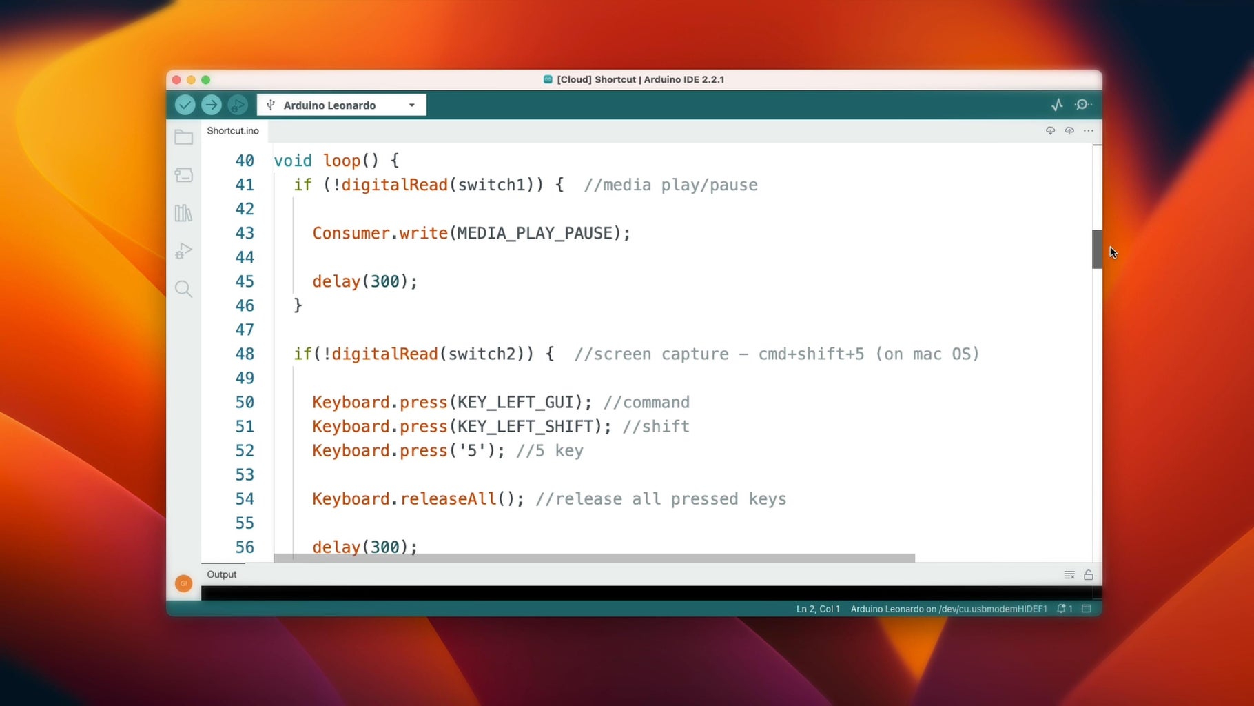
if(!digitalRead(switch2)) { //screen capture - cmd+shift+5 (on mac OS)
Keyboard.press(KEY_LEFT_GUI); //command
Keyboard.press(KEY_LEFT_SHIFT); //shift
Keyboard.press('5'); //5 key
Keyboard.releaseAll(); //release all pressed keys
delay(300);
}
In the loop I created an if condition for each button to execute functions when the switch is pressed. For example, to key number 2 I assigned the shortcut to take a screenshot, which on Mac OS is CMD+SHIFT+5. With an if condition, if the button is pressed, the Arduino sends the three key presses to the computer with the Keyboard.press() function. Then the keys are released with the Keyboard.releaseAll() function. I also added a small delay to prevent the commands from being repeated (debouncing the switch). The Keyboard.press() function accepts letters, numbers (in this format: 'a') and modifier keys (like Command, CTRL, SHIFT, ALT...). The table with all the modifier keys you can use can be found at this page.
  if (!digitalRead(switch5)) {  //save - cmd+s (on mac OS)

    Keyboard.press(KEY_LEFT_GUI); //command
    Keyboard.press('s'); //S key

    Keyboard.releaseAll(); //release all pressed keys

    delay(300);
  }
I wrote an if condition for all 12 buttons, entering the keys of the different shortcuts that are associated to each button of the keyboard. In this example we have the "save" key, that sends the CMD+S (CTRL+S on Windows) shortcut to the computer.
  if (!digitalRead(switch1)) {  //media play/pause

    Consumer.write(MEDIA_PLAY_PAUSE);

    delay(300);
  }
In this other example you can see how to use the keyboard "consumer keys", that include the key to play and pause music and, for example, the one for skipping to the next track. Here you can see the full list of these commands.
#include "HID-Project.h"
...

int FinderView = 0;

void setup() {
  ...
}

void loop() {
  ...

  if ((!digitalRead(switch6)) && FinderView == 0) {  //change Finder view to gallery - cmd+4 (on mac OS)

    Keyboard.press(KEY_LEFT_GUI); //command
    Keyboard.press('4'); //4 key

    Keyboard.releaseAll(); //release all pressed keys

    FinderView = 1;

    delay(300);
  }

  if ((!digitalRead(switch6)) && FinderView == 1) {  //change Finder view to icons - cmd+1 (on mac OS)

    Keyboard.press(KEY_LEFT_GUI); //command
    Keyboard.press('1'); //1 key

    Keyboard.releaseAll(); //release all pressed keys

    FinderView = 2;

    delay(300);
  }

  if ((!digitalRead(switch6)) && FinderView == 2) {  //change Finder view to list - cmd+2 (on mac OS)

    Keyboard.press(KEY_LEFT_GUI); //command
    Keyboard.press('2'); //2 key

    Keyboard.releaseAll(); //release all pressed keys

    FinderView = 0;

    delay(300);
  }
This example shows how you can make one switch of the macro keyboard cycle through different shortcuts each time it is pressed. In order to do this you need an extra variable at the beginning of the code. In the if conditions, you both need to check wether the switch is pressed and if the variable has the correct value. Inside the condition you then set the variable to the value that's in the if condition of the next shortcut you want to be pressed. In my case, I used this system to cycle through the different views (grid, list, gallery...) of the File Explorer. In the code you can see the shortcuts that switch to the different views.
This is how the code for this project works. As you have seen it is quite simple to change the code to insert the shortcuts you want to associate to the keys of your keyboard. Please note that all the shortcuts that are written in my code work on Mac OS. If you have a Windows PC you will have to modify the key presses that are sent to the computer for each shortcut in the Arduino code.
The HID-Project library has many very interesting functions, so I recommend that you take a look at the various examples on the Github page.
When you have written or pasted the code into the Arduino IDE, you can connect the Arduino to your computer to upload the code. Once the upload has finished, the keyboard is ready to be used.
Here you can find the full code:
#include "HID-Project.h"

const int switch1 = 2;
const int switch2 = 3;
const int switch3 = 4;
const int switch4 = 5;
const int switch5 = 6;
const int switch6 = 7;
const int switch7 = 8;
const int switch8 = 9;
const int switch9 = 10;
const int switch10 = 16;
const int switch11 = 14;
const int switch12 = 15;

int FinderView = 0;

void setup() {
  pinMode(switch1, INPUT_PULLUP);
  pinMode(switch2, INPUT_PULLUP);
  pinMode(switch3, INPUT_PULLUP);
  pinMode(switch4, INPUT_PULLUP);
  pinMode(switch5, INPUT_PULLUP);
  pinMode(switch6, INPUT_PULLUP);
  pinMode(switch7, INPUT_PULLUP);
  pinMode(switch8, INPUT_PULLUP);
  pinMode(switch9, INPUT_PULLUP);
  pinMode(switch10, INPUT_PULLUP);
  pinMode(switch11, INPUT_PULLUP);
  pinMode(switch12, INPUT_PULLUP);

  // Sends a clean report to the host. This is important on any Arduino type.
  Keyboard.begin();
  Consumer.begin();
}

void loop() {
  if (!digitalRead(switch1)) {  //media play/pause

    Consumer.write(MEDIA_PLAY_PAUSE);

    delay(300);
  }

  if(!digitalRead(switch2)) {  //screen capture - cmd+shift+5 (on mac OS)

    Keyboard.press(KEY_LEFT_GUI); //command
    Keyboard.press(KEY_LEFT_SHIFT); //shift
    Keyboard.press('5'); //5 key

    Keyboard.releaseAll(); //release all pressed keys

    delay(300);
  }

  if (!digitalRead(switch3)) {  //redo - cmd+shift+z (on mac OS)

    Keyboard.press(KEY_LEFT_GUI); //command
    Keyboard.press(KEY_LEFT_SHIFT); //shift
    Keyboard.press('z'); //Z key

    Keyboard.releaseAll(); //release all pressed keys

    delay(300);
  }

  if (!digitalRead(switch4)) {  //undo - cmd+z (on mac OS)

    Keyboard.press(KEY_LEFT_GUI); //command
    Keyboard.press('z'); //Z key

    Keyboard.releaseAll(); //release all pressed keys

    delay(300);
  }

  if (!digitalRead(switch5)) {  //save - cmd+s (on mac OS)

    Keyboard.press(KEY_LEFT_GUI); //command
    Keyboard.press('s'); //S key

    Keyboard.releaseAll(); //release all pressed keys

    delay(300);
  }

  if ((!digitalRead(switch6)) && FinderView == 0) {  //change Finder view to gallery - cmd+4 (on mac OS)

    Keyboard.press(KEY_LEFT_GUI); //command
    Keyboard.press('4'); //4 key

    Keyboard.releaseAll(); //release all pressed keys

    FinderView = 1;

    delay(300);
  }

  if ((!digitalRead(switch6)) && FinderView == 1) {  //change Finder view to icons - cmd+1 (on mac OS)

    Keyboard.press(KEY_LEFT_GUI); //command
    Keyboard.press('1'); //1 key

    Keyboard.releaseAll(); //release all pressed keys

    FinderView = 2;

    delay(300);
  }

  if ((!digitalRead(switch6)) && FinderView == 2) {  //change Finder view to list - cmd+2 (on mac OS)

    Keyboard.press(KEY_LEFT_GUI); //command
    Keyboard.press('2'); //2 key

    Keyboard.releaseAll(); //release all pressed keys

    FinderView = 0;

    delay(300);
  }

  if (!digitalRead(switch7)) {  //select all - cmd+a (on mac OS)

    Keyboard.press(KEY_LEFT_GUI); //command
    Keyboard.press('a'); //A key

    Keyboard.releaseAll(); //release all pressed keys

    delay(300);
  }

  if (!digitalRead(switch8)) {  //move files - cmd+option+v (on mac OS)

    Keyboard.press(KEY_LEFT_GUI); //command
    Keyboard.press(KEY_LEFT_ALT); //option
    Keyboard.press('v'); //V key

    Keyboard.releaseAll(); //release all pressed keys

    delay(300);
  }

  if (!digitalRead(switch9)) {  //hide window - cmd+h (on mac OS)

    Keyboard.press(KEY_LEFT_GUI); //command
    Keyboard.press('h'); //H key

    Keyboard.releaseAll(); //release all pressed keys

    delay(300);
  }

  if (!digitalRead(switch10)) {  //copy - cmd+c (on mac OS)

    Keyboard.press(KEY_LEFT_GUI); //command
    Keyboard.press('c'); //C key

    Keyboard.releaseAll(); //release all pressed keys

    delay(300);
  }

  if (!digitalRead(switch11)) {  //cut - cmd+x (on mac OS)

    Keyboard.press(KEY_LEFT_GUI); //command
    Keyboard.press('x'); //X key

    Keyboard.releaseAll(); //release all pressed keys

    delay(300);
  }

  if (!digitalRead(switch12)) {  //paste - cmd+v (on mac OS)

    Keyboard.press(KEY_LEFT_GUI); //command
    Keyboard.press('v'); //V key

    Keyboard.releaseAll(); //release all pressed keys

    delay(300);
  }
}
Step 8: Finished!

Overall, I am very happy with how this macro keyboard came out, and it looks very nice on my desk. I have been using my macro keyboard for over 2 weeks, and I can assure that it will make you save quite a bit of time when working on the computer and it is really convenient, both for video editing and for general use. I hope you found this guide interesting and maybe useful. To see more details about this project, watch the video on my YouTube channel. Bye!


![Tim's Mechanical Spider Leg [LU9685-20CU]](https://content.instructables.com/FFB/5R4I/LVKZ6G6R/FFB5R4ILVKZ6G6R.png?auto=webp&crop=1.2%3A1&frame=1&width=306)


